")
 English
 Español (México)
FLEXURAL STRENGTHENING OF CONCRETE BEAMS WITH CFRP
This article presents the effectiveness of carbon fiber reinforced polymer (CFRP) as a flexural strengthening system for RC beams.
1. A short review of flexural cracks
Flexural cracks of the RC beam start at the tensile zone and will expand up to the neutral axis of the beam. The width of flexural cracks stays narrow in short term but under continuous loading, they will expand over time. It has been proven that cracks will appear uniformly spaced along the most heavily loaded portion of the beam, i.e., near the mid-span in sagging or over the supports in hogging (refer to Figure 1). Flexural cracks will appear when:- The flexural capacity of the beam is inadequate.
- When cross-section of the beam or main reinforcement in the beam is insufficient.
- When it is loaded more than defined loads.

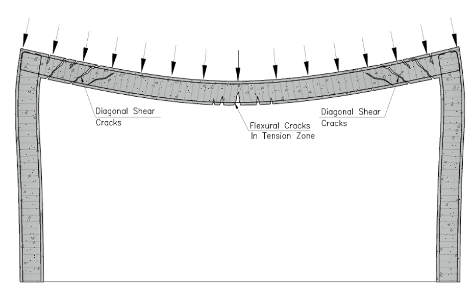
Figure 1- Schematic view of RC concrete cracks
2. Shear cracks and flexural cracks
According to ACI 440-2R beams shall be strengthened in a way that under over-load conditions, the CFRP strengthened beam fails in the flexural mode rather than in a shear mode, so while analyzing a flexural strengthened beam, it should be checked for shear capacity as well. According to various investigations on this issue, it has been proven that over-strengthening in shear resulted in bending failure in some cases, but after strengthening the beams for bending, shear failure was achieved. The potential for shear failure of the beam should be considered by comparing the available shear of the section to the shear strength of the section. If the available shear of the section is more than the shear strength of that, in addition to flexural strips, CFRP strips at 45° to the axis of the beam is beneficial to resist shear forces [1].3. Advantages of CFRP as a flexural strengthening system
- It has been concluded that as CFRP can tolerate more deformation, the concrete specimen which has been strengthened with CFRP is more ductile [2].
- It has been concluded that U-shaped CFRP in beams gives the best results in improving the flexural strength because its contribution in the redistribution of the internal forces through greater deformations of the beam is more than other types of wrapping[2].
- CFRP is generally applied on the faces of beams by an external bonding reinforcing technique (EBR)[3].
4. Near-surface mounted (NSM) strengthening technique
One technique of flexural strengthening of RC beams is the near-surface mounted (NSM) strengthening technique. According to [3] the NSM technique significantly increases the amount of tolerable load at serviceability limit state, as well as the stiffness after concrete cracking.In the near-surface mounted (NSM) strengthening technique, CFRP strips insert into pre-cut grooves through concrete cover at the tension zone of the member to be strengthened. For bonding of the CFRP strips to the concrete, a high-strength epoxy adhesive will be used (Figure 2&3).
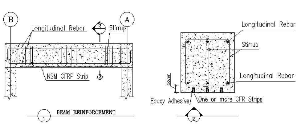
Figure 2- Schematic view of NSM technique
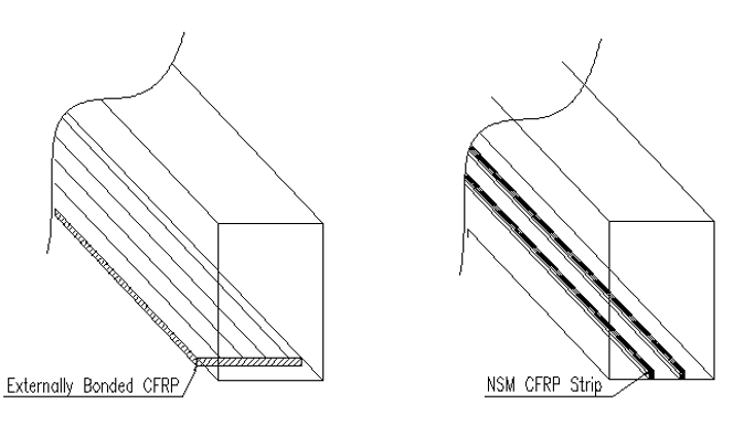
Figure 3- Differences of strengthening techniques (EBR vs. NSM)
According to Blaschko and Zilch, and Barros and Fortes, by using the NSM technique peeling can be prevented and the tensile strain of the CFRP touches values around its ultimate strain [3].
To assess the efficiency of the NSM method in the flexural strengthening of the beams, four series of beams were tested under four types of point loads [3]. By increasing the load in serviceability and at ultimate states, the beam’s stiffness, the maximum strain of CFRP, and the beam’s deflection capacity (an indicator of ductility) were measured.
From these series of tests, it has been assured an average increase of 91% on the ultimate load of a CFRP strengthened beam. Furthermore, the below results have been taken as well:
The ultimate flexural capacity of the strengthened RC beam exceeds that of the non-strengthened RC beam by 20.7% [4]. The failure process of RC beams understudies have shown that the main reason for CFRP strengthened beam failure is the debonding of CFRP sheets caused by crack development in the mid-span of RC beams [4].
On the other hand, by improving the confinement effect of a CFRP sheet by increasing the number of layers of CFRP sheets, the deflection of strengthened RC beam improves, for example, according to [4] the deflection of an RC beam strengthened by two layers of CFRP is about 42% smaller than that of the one-layer sheet under the same load.
In figure 4 you can see one of the Rhino Carbon Fiber™ Company’s concrete beam strengthening projects. In this project after developing a structural design, the Rhino Carbon Fiber™ Company used 3, 4 and 5 layers of CFRP to meet the technical requirements of the structural design, which was very difficult due to the humidity, heat and access restrictions. The project included over 500 square meters of Rhino Carbon Fiber™ CFRP applied with RCF™ saturant-adhesive epoxy.
After performing load tests on the strengthened beams, only a fraction of the deflection that was expected (7-8mm was expected and the beams deflected less than 1mm) was observed. So, the building successfully reinforced, while staying on schedule, due to immediate product availability and ease of installation.
To assess the efficiency of the NSM method in the flexural strengthening of the beams, four series of beams were tested under four types of point loads [3]. By increasing the load in serviceability and at ultimate states, the beam’s stiffness, the maximum strain of CFRP, and the beam’s deflection capacity (an indicator of ductility) were measured.
From these series of tests, it has been assured an average increase of 91% on the ultimate load of a CFRP strengthened beam. Furthermore, the below results have been taken as well:
4.1 Deflection
It has been seen that by using CFRP laminate strips the tolerable load at the onset of yielding has been subjected to a great increase of about 32~47%. Also, the service load (the load in which under that load the deflection of the beam will stay under allowable deflection of L/360 for Live load and/or L/240 for Dead+Live load) for the strengthened beam has an increase of 45%.4.1 Force-Strain Relationship
According to 4 tests conducted in an investigation [3], CFRP laminates have reached 62~91% of their ultimate strain. In other words, it indicates that the stress level of beams strengthened with the NSM technique will increase up to the tensile strength of CFRP. According to tests results, by increasing applied loads, first of all concrete will crack, secondly, reinforcement will yield and finally, CFRP begins sliding up to the development of the failure surface. It is obvious that the strain ratio increases due to a decrease in the beam’s stiffness.4.3 Stiffness
Studies show lower deflection in CFRP-strengthened beams with the NSM technique, which is the indication of an increase in beam stiffness. The rate of increase in stiffness of the CFRP strengthened beam with the NSM technique compared to ordinary beams under the same loading conditions is 32%.5. The failure mode of non-strengthened vs. CFRP-strengthened RC beam
5.1 Non-strengthened RC beam
In the first stage of loading, there is a linear increase in the strain of concrete and tensile steel bars, then the first flexural cracks will appear at the mid-span of the beam. The next phase is the stage of crack development in which the width of cracks will increase with increased load. Continuously increasing the load, tensile steel bars yield, the concrete cover gradually peels off and strain of concrete and steel bars speeds up. Next, by continuously increasing the load the concrete in the compression zone will crush and eventually fails [4].5.2 CFRP-strengthened RC beam
First of all, by increasing the load, linear strain increases in the concrete, steel bars and CFRP sheets. By increasing the load, several vertical cracks will appear at the mid-span of the RC beam. As the load increases, the strengthened RC beams have more and thinner crack width in comparison with the non-strengthened RC beams due to the effect of CFRP sheets. As the load increases some noise from the bottom of the beam can be heard and the failure occurs suddenly when the CFRP sheet splits from the RC beam.The ultimate flexural capacity of the strengthened RC beam exceeds that of the non-strengthened RC beam by 20.7% [4]. The failure process of RC beams understudies have shown that the main reason for CFRP strengthened beam failure is the debonding of CFRP sheets caused by crack development in the mid-span of RC beams [4].
6. Effect of number of CFRP sheet layers on load-deflection relationship
The ultimate flexural bearing capacity of the beam strengthened by different layers of the CFRP sheets increases with the increase of CFRP sheet layers. However, by increasing CFRP layers the coordination between these layers plays an important role in the flexural bearing capacity of the beam, and by decreasing this coordination the efficiency of CFRP sheets decreases.On the other hand, by improving the confinement effect of a CFRP sheet by increasing the number of layers of CFRP sheets, the deflection of strengthened RC beam improves, for example, according to [4] the deflection of an RC beam strengthened by two layers of CFRP is about 42% smaller than that of the one-layer sheet under the same load.
In figure 4 you can see one of the Rhino Carbon Fiber™ Company’s concrete beam strengthening projects. In this project after developing a structural design, the Rhino Carbon Fiber™ Company used 3, 4 and 5 layers of CFRP to meet the technical requirements of the structural design, which was very difficult due to the humidity, heat and access restrictions. The project included over 500 square meters of Rhino Carbon Fiber™ CFRP applied with RCF™ saturant-adhesive epoxy.
After performing load tests on the strengthened beams, only a fraction of the deflection that was expected (7-8mm was expected and the beams deflected less than 1mm) was observed. So, the building successfully reinforced, while staying on schedule, due to immediate product availability and ease of installation.
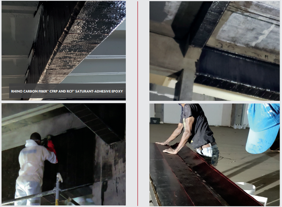
Figure 4- Concrete beam strengthening project by Rhino Carbon Fiber™
In the end, CFRP flexural strengthened beams have been recorded up to 160% increase in their flexural strength, but according to strengthening, ductility and serviceability limitations of ACI-440, increasing in flexural strength of the member up to 40% is more reasonable.
Authors
Parastoo Azad and Dr. Mehrtash Soltani (January 15, 2020)
References
Parastoo Azad and Dr. Mehrtash Soltani (January 15, 2020)
References
- ConcreteSociety, 1996. [Online]. Available: http://www.concrete.org.uk/fingertips-nuggets.asp?cmd=display&id=185.
- S. A. M. C. N. Attari, “Flexural strengthening of concrete beams using CFRP, GFRP and hybrid FRP sheets,” Construction and Building Materials, pp. 746-757, 2012.
- A. F. J.A.O. Barros, “Flexural strengthening of concrete beams with CFRP laminates bonded into slits,” Cement and Concrete Composites, pp. 471-480, 2005.
- H. Z. N. J. Y. F. J. S. C. F. Y. G. Feng Yu, “Flexural experiment and capacity investigation of CFRP repaired RC beams under heavy pre-damaged level,” Construction and Building Materials, vol. 230, 2020.
- S. E.-R. S. G. A.F Ashour, “Flexural strengthening of RC continuous beams using CFRP laminates,” Cement and Concrete Composites, pp. 765-775, 2004.
- CI440, Guide for the Design and Construction of Externally Bonded FRP Systems for Strengthening Concrete Structures, Michigan, USA: American Concrete Institute, 2017.
FLEXURAL STRENGTHENING OF CONCRETE BEAMS WITH CFRP
This article presents the effectiveness of carbon fiber reinforced polymer (CFRP) as a flexural strengthening system for RC beams.
1. A short review of flexural cracks
Flexural cracks of the RC beam start at the tensile zone and will expand up to the neutral axis of the beam. The width of flexural cracks stays narrow in short term but under continuous loading, they will expand over time. It has been proven that cracks will appear uniformly spaced along the most heavily loaded portion of the beam, i.e., near the mid-span in sagging or over the supports in hogging (refer to Figure 1). Flexural cracks will appear when:- The flexural capacity of the beam is inadequate.
- When cross-section of the beam or main reinforcement in the beam is insufficient.
- When it is loaded more than defined loads.
Figure 1- Schematic view of RC concrete cracks
2. Shear cracks and flexural cracks
According to ACI 440-2R beams shall be strengthened in a way that under over-load conditions, the CFRP strengthened beam fails in the flexural mode rather than in a shear mode, so while analyzing a flexural strengthened beam, it should be checked for shear capacity as well. According to various investigations on this issue, it has been proven that over-strengthening in shear resulted in bending failure in some cases, but after strengthening the beams for bending, shear failure was achieved. The potential for shear failure of the beam should be considered by comparing the available shear of the section to the shear strength of the section. If the available shear of the section is more than the shear strength of that, in addition to flexural strips, CFRP strips at 45° to the axis of the beam is beneficial to resist shear forces [1].3. Advantages of CFRP as a flexural strengthening system
- It has been concluded that as CFRP can tolerate more deformation, the concrete specimen which has been strengthened with CFRP is more ductile [2].
- It has been concluded that U-shaped CFRP in beams gives the best results in improving the flexural strength because its contribution in the redistribution of the internal forces through greater deformations of the beam is more than other types of wrapping[2].
- CFRP is generally applied on the faces of beams by an external bonding reinforcing technique (EBR)[3].
4. Near-surface mounted (NSM) strengthening technique
One technique of flexural strengthening of RC beams is the near-surface mounted (NSM) strengthening technique. According to [3] the NSM technique significantly increases the amount of tolerable load at serviceability limit state, as well as the stiffness after concrete cracking.In the near-surface mounted (NSM) strengthening technique, CFRP strips insert into pre-cut grooves through concrete cover at the tension zone of the member to be strengthened. For bonding of the CFRP strips to the concrete, a high-strength epoxy adhesive will be used (Figure 2&3).
Figure 2- Schematic view of NSM technique
Figure 3- Differences of strengthening techniques (EBR vs. NSM)
According to Blaschko and Zilch, and Barros and Fortes, by using the NSM technique peeling can be prevented and the tensile strain of the CFRP touches values around its ultimate strain [3].
To assess the efficiency of the NSM method in the flexural strengthening of the beams, four series of beams were tested under four types of point loads [3]. By increasing the load in serviceability and at ultimate states, the beam’s stiffness, the maximum strain of CFRP, and the beam’s deflection capacity (an indicator of ductility) were measured.
From these series of tests, it has been assured an average increase of 91% on the ultimate load of a CFRP strengthened beam. Furthermore, the below results have been taken as well:
The ultimate flexural capacity of the strengthened RC beam exceeds that of the non-strengthened RC beam by 20.7% [4]. The failure process of RC beams understudies have shown that the main reason for CFRP strengthened beam failure is the debonding of CFRP sheets caused by crack development in the mid-span of RC beams [4].
On the other hand, by improving the confinement effect of a CFRP sheet by increasing the number of layers of CFRP sheets, the deflection of strengthened RC beam improves, for example, according to [4] the deflection of an RC beam strengthened by two layers of CFRP is about 42% smaller than that of the one-layer sheet under the same load.
In figure 4 you can see one of the Rhino Carbon Fiber™ Company’s concrete beam strengthening projects. In this project after developing a structural design, the Rhino Carbon Fiber™ Company used 3, 4 and 5 layers of CFRP to meet the technical requirements of the structural design, which was very difficult due to the humidity, heat and access restrictions. The project included over 500 square meters of Rhino Carbon Fiber™ CFRP applied with RCF™ saturant-adhesive epoxy.
After performing load tests on the strengthened beams, only a fraction of the deflection that was expected (7-8mm was expected and the beams deflected less than 1mm) was observed. So, the building successfully reinforced, while staying on schedule, due to immediate product availability and ease of installation.
To assess the efficiency of the NSM method in the flexural strengthening of the beams, four series of beams were tested under four types of point loads [3]. By increasing the load in serviceability and at ultimate states, the beam’s stiffness, the maximum strain of CFRP, and the beam’s deflection capacity (an indicator of ductility) were measured.
From these series of tests, it has been assured an average increase of 91% on the ultimate load of a CFRP strengthened beam. Furthermore, the below results have been taken as well:
4.1 Deflection
It has been seen that by using CFRP laminate strips the tolerable load at the onset of yielding has been subjected to a great increase of about 32~47%. Also, the service load (the load in which under that load the deflection of the beam will stay under allowable deflection of L/360 for Live load and/or L/240 for Dead+Live load) for the strengthened beam has an increase of 45%.4.1 Force-Strain Relationship
According to 4 tests conducted in an investigation [3], CFRP laminates have reached 62~91% of their ultimate strain. In other words, it indicates that the stress level of beams strengthened with the NSM technique will increase up to the tensile strength of CFRP. According to tests results, by increasing applied loads, first of all concrete will crack, secondly, reinforcement will yield and finally, CFRP begins sliding up to the development of the failure surface. It is obvious that the strain ratio increases due to a decrease in the beam’s stiffness.4.3 Stiffness
Studies show lower deflection in CFRP-strengthened beams with the NSM technique, which is the indication of an increase in beam stiffness. The rate of increase in stiffness of the CFRP strengthened beam with the NSM technique compared to ordinary beams under the same loading conditions is 32%.5. The failure mode of non-strengthened vs. CFRP-strengthened RC beam
5.1 Non-strengthened RC beam
In the first stage of loading, there is a linear increase in the strain of concrete and tensile steel bars, then the first flexural cracks will appear at the mid-span of the beam. The next phase is the stage of crack development in which the width of cracks will increase with increased load. Continuously increasing the load, tensile steel bars yield, the concrete cover gradually peels off and strain of concrete and steel bars speeds up. Next, by continuously increasing the load the concrete in the compression zone will crush and eventually fails [4].5.2 CFRP-strengthened RC beam
First of all, by increasing the load, linear strain increases in the concrete, steel bars and CFRP sheets. By increasing the load, several vertical cracks will appear at the mid-span of the RC beam. As the load increases, the strengthened RC beams have more and thinner crack width in comparison with the non-strengthened RC beams due to the effect of CFRP sheets. As the load increases some noise from the bottom of the beam can be heard and the failure occurs suddenly when the CFRP sheet splits from the RC beam.The ultimate flexural capacity of the strengthened RC beam exceeds that of the non-strengthened RC beam by 20.7% [4]. The failure process of RC beams understudies have shown that the main reason for CFRP strengthened beam failure is the debonding of CFRP sheets caused by crack development in the mid-span of RC beams [4].
6. Effect of number of CFRP sheet layers on load-deflection relationship
The ultimate flexural bearing capacity of the beam strengthened by different layers of the CFRP sheets increases with the increase of CFRP sheet layers. However, by increasing CFRP layers the coordination between these layers plays an important role in the flexural bearing capacity of the beam, and by decreasing this coordination the efficiency of CFRP sheets decreases.On the other hand, by improving the confinement effect of a CFRP sheet by increasing the number of layers of CFRP sheets, the deflection of strengthened RC beam improves, for example, according to [4] the deflection of an RC beam strengthened by two layers of CFRP is about 42% smaller than that of the one-layer sheet under the same load.
In figure 4 you can see one of the Rhino Carbon Fiber™ Company’s concrete beam strengthening projects. In this project after developing a structural design, the Rhino Carbon Fiber™ Company used 3, 4 and 5 layers of CFRP to meet the technical requirements of the structural design, which was very difficult due to the humidity, heat and access restrictions. The project included over 500 square meters of Rhino Carbon Fiber™ CFRP applied with RCF™ saturant-adhesive epoxy.
After performing load tests on the strengthened beams, only a fraction of the deflection that was expected (7-8mm was expected and the beams deflected less than 1mm) was observed. So, the building successfully reinforced, while staying on schedule, due to immediate product availability and ease of installation.
Figure 4- Concrete beam strengthening project by Rhino Carbon Fiber™
In the end, CFRP flexural strengthened beams have been recorded up to 160% increase in their flexural strength, but according to strengthening, ductility and serviceability limitations of ACI-440, increasing in flexural strength of the member up to 40% is more reasonable.
Authors
Parastoo Azad and Dr. Mehrtash Soltani (January 15, 2020)
References
Parastoo Azad and Dr. Mehrtash Soltani (January 15, 2020)
References
- ConcreteSociety, 1996. [Online]. Available: http://www.concrete.org.uk/fingertips-nuggets.asp?cmd=display&id=185.
- S. A. M. C. N. Attari, “Flexural strengthening of concrete beams using CFRP, GFRP and hybrid FRP sheets,” Construction and Building Materials, pp. 746-757, 2012.
- A. F. J.A.O. Barros, “Flexural strengthening of concrete beams with CFRP laminates bonded into slits,” Cement and Concrete Composites, pp. 471-480, 2005.
- H. Z. N. J. Y. F. J. S. C. F. Y. G. Feng Yu, “Flexural experiment and capacity investigation of CFRP repaired RC beams under heavy pre-damaged level,” Construction and Building Materials, vol. 230, 2020.
- S. E.-R. S. G. A.F Ashour, “Flexural strengthening of RC continuous beams using CFRP laminates,” Cement and Concrete Composites, pp. 765-775, 2004.
- CI440, Guide for the Design and Construction of Externally Bonded FRP Systems for Strengthening Concrete Structures, Michigan, USA: American Concrete Institute, 2017.